
Advertisements
Micro Controller Based Industrial Motor Speed Control Project material PDF document download start from the abstract to chapters 1 to 5.
CHAPTER THREE
PRINCIPLES OF OPERATION AND CONSTRUCTION OF MICRO CONTROLLER BASED INDUSTRIAL MOTOR SPEED CONTROL
Principles of Operation
All microcontroller systems works with a program uploaded into the chip.
The program was written in assembly language after which the executable file was uploaded to the chip through a programmer.
Advertisements
Below is the mode of operation
- At power on the microcontroller resets to ensure that the program starts from the first program and ensures that all outputs are switched low also displaying SPO indicating speed zero.
- Then the MCU keeps scanning the two taping switch either to increase or decrease the speed of the motor and displays the speed levels SPO,SP1,SP2, SP3, SP4 or SP5, as while.
- Once a valid signal is seen the MCU calculates the required speed and acts as necessary by either increasing or reducing the speed of the motor as while as displaying the level of motor speed and jumps to stage two.
BLOCK DIAGRAM
HOW THE CIRCUIT WORKS
How the circuit works can be best understood by taken an analysis of the different sections of the block diagram
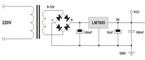
Power supply
The project makes use of 12volts rectified power from mains power. Below shows a suitable power supply need for the project.
Input unit
This unit is made up of the taping switches, that are used to increase the speed or reduces the speed of the motor.
Microcontroller and Buffers unit
In this project work the microcontroller forms the core of the system, meaning that all mathematical and logical operation of the system is executed from within it as explained in the principles of operation.
Buffer:
The ULM2003 is used as a buffer, the buffer isolates the microcontroller from the display unit and also prevents the display from drawing excess current from the microcontroller thereby supplying the current needed to the seven segment display.
VISUAL DISPLAY UNIT
The visual display unit is used to show the current value of calculated speed level at any point in time. It is built around the microcontroller which serves as the core for the system by outputting the desired values of information unto the display a multiplexed seven segment display is used in this project. Basically, LED displays are nothing else but several LEDs molded in the same plastic case. Diodes are arranged so that different marks-commonly digits: 0, 1, and 2…9 are displayed by activating them. There are many types of displays composed of several dozens of built in diodes which can display different symbols.
The most commonly used are so called 7-segment displays. They are composed of 8 LEDs, 7 segments are arranged as a rectangle for symbol displaying and there is additional segment for decimal point displaying. In order to simplify connecting, anodes and cathodes of all diodes are connected to the common pin so that there are common cathode displays and common anode displays. Segments are marked with the litters A to G as shown on the figure on below. When connecting, each diode is treated independently, which means that each must have its own conductor for current limitation.
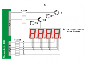
When connecting displays to the microcontroller, the greatest problem is a great deal of valuable I/O pins which they “occupy”, especially if it is needed to display several-digit numbers. Problem is more than obvious if for example it is needed to display two 6-digit numbers (a simple calculation shows that 96 output pins are needed)!The solution on this problem is called MULTIPLEXING. This is how optical illusion based on the same operating principle as film camera occurs. The principle is that only one digit is active but by quick changing one gets impression that all digits of a number are active at the same time.
COMPONENTS USED AND FUNCTIONS
An electronic circuit is a collection of components connected together to perform a particular electronic function. Each component has its part to play in the operation of the circuit if any component should fail then the operation will be drastically changed.
Generally, any project construction must consist of electrical and electronics components which are often assembled together according to electrical laws. This project makes use of the following components discussed below
DESCRIPTION OF COMPONENTS
RESISTORS:
Resistor is a component, which aims to determine current in a certain branch in electric circuit according to Ohm’s Law depending on the resistor value and the voltage upon it. Every conductor has its own resistance. The resistance depends on the material resistively, its length and its cross-section area, the most commonly used resistors come in cylindrical packages with 4 colored rings – three are close to each other and one is slightly away. Three close rings indicate value of the resistor and the forth its tolerance. The following table shows connection between specific color and a digit from which a value can be determined.
| Black | 0 |
| Brown | 1 |
| Red | 2 |
| Orange | 3 |
| Yellow | 4 |
| Green | 5 |
| Blue | 6 |
| Purple | 7 |
| Grey | 8 |
| White | 9 |
| Gold | 5% |
| Silver | 10% |
To determine resistor’s value we must write down its colors in the way that gold or silver will be the last one. Then we will translate the colors to digits. The first two digits indicate first two digits in the resistor’s value and the third tells us the number of zeros we should add after the former two.
In the following example, resistor’s colors are: brown, black and red.
That means that the resistor’s value is 1 0 and two zeros, we get 1 0 0 0 ohm or 1K(.
Tolerance indicates how precise the resistor’s value is. For example, if you will measure the 1K( resistor with 5% tolerance, we may expect its resistance to be in the range from 950( to 1050(.
CAPACITORS
These are devices that might be considered simply frequency dependent resistors. A capacitors is more complicated than a resistor, the current is not simply proportional to the voltage, but rather to the rate of change of voltage. Capacitors consist of two metal plates that are separated by an insulating material .If a battery is connected to both plates; an electric charge will flow for a short time and accumulate on each plate. If the battery is disconnected, the capacitor retains the charge and the voltage associated with it. Rapidly changing voltages, such as caused by an audio or radio signal, produce larger current flows to and from the plates; the capacitor then functions as a conductor for the changing current. This effect can be used, for example, to separate an audio or radio signal from a direct current in order to connect the output of one amplifier stage to the input of the next amplifier stage.
Capacitors are employed in circuits for any of the following purposes; bypass, coupling, filtering, energy storage and resonant circuits.
DIODES
Diodes allow electricity to flow in only one direction. The arrow of the circuit symbol shows the direction in which the current can flow. Diodes are the electrical version of a valve and early diodes were actually called valves.
FORWARD VOLTAGE DROP
Electricity uses up a little energy pushing its way through the diode, rather like a person pushing through a door with a spring. This means that there is a small voltage across a conducting diode which is called the forward voltage drop, and is about 0.7V for all normal diodes which are made from silicon. The forward voltage drop of a diode is almost constant irrespective of the value of current passing through it, the reason for their steep characteristic (current-voltage graph).
REVERSE VOLTAGE
When a reverse voltage is applied, a perfect diode does not conduct. Though all real diodes leak very tiny currents of few micro amperes, this can be ignored in most circuits because it will be very much smaller than the current flowing in the forward direction. However, all diodes have a maximum reverse voltage (usually 50V or more) and if this is exceeded, the diode breaks down and passes a large current in the reverse direction.
Ordinary diodes can be split into two types: Signal diodes, which pass small currents of 100mA or less, and Rectifier diodes, which can pass large currents.
Diodes must be connected properly. The cathode is marked by a line painted on the body. Diodes are labeled with their codes in small prints.
Germanium diodes (OA90) have a lower forward voltage drop of 0.2V and this makes them suitable to be used in this project as detectors which extract the audio signal from the weak radio signal.
Advertisements
